Saturday, August 15, 2015

Salt Cell Failure - Post-mortem with pictures

My hayward T-15 salt water generator cell decided to up and die after 9 years, so I decided to find out a) what causes it, and b)if it is repairable. 

For those who are too impatient to read to the end the answer to B) is Yes and No. Yes, it is *easily* repairable. No, because the cells have been designed so as make them non-serviceable. Quite frankly this makes me a bit perturbed as it makes ABSOLUTELY no sense to spend $500 when a $50 repair will suffice. Now, on to dissection.


The salt cell as it was removed. It was provided by the pool builder, and has been in service since summer 2003. The seam underneath the label is melted or welded together, and survived quite a few sharp blows that I was hoping would cause the seam to fail.


Cover removal is accomplished by flipping the unit and slipping a screwdriver into the gap. It simply snap over a plastic pin (bottom center) and comes off easily.
The black substance on the left hand sensor is hard, apparently some type of epoxy. The black stuff at the top, which can be seen running, is like cooled tar and can be dug out as we will see shortly.


The tar dug out, revealing three screw on connections. Two black (cathode) and one white (anode), with the blacks jumpered together. These correspond to connector pins 1,3 and 2,4 as seen with the connector facing you. Red and blue connect to pins 8 and 10.


The cell cut open. Only plates 1, 7, and 13 are connected. 2-6 and 8-12 are simply held in place by the plastic guides. These plates correspond directly to the connections seen above.


Visible on the bench are the 10 loose plates. As you can see, they show VERY LITTLE evidence of erosion and no evidence of scale or calcium buildup.


It quickly became apparent that the edge plates were held fast, while the center plate was loose. It pulled out easily to reveal the contact post had corroded in half. 

Note: This cell failed suddenly after 9 years of perfect service. Obviously at some point the contact post (which appears to be brass) separated because of galvanic corrosion. Not really a surprise as the anode only has one connection, while the cathodes have two.


 A close up of the failed center stud. Plate erosion is minimal.


All three plates together


Comparing a good edge post with the failed center post.


 Looking down into the cell (plate guide removed), you can see what remains of the center post.


The full set of plates, in the order they appear in the assembled cell. Again, note almost ZERO erosion on the unconnected plates, and only minimal erosion on the cathodes.


And finally a close up of the "active" plates next to the "passive" plates. As you can see, actual damage to the plates is minimal.


A cleaned up uncorroded post.


The housing with remaining anode post and cathode posts removed


 In my opinion, there is absolutely no reason for these cells to be non-serviceable. Even if the entire plate assembly had to be recycled/replaced, the tail cap should come off, three nuts removed, and the plate assembly drops out. Re-insert, reassemble, carry on. The initial cost of such a housing would be more, but the guts could be replaced every few years for a small fraction of the cost of a disposable unit.

After 9 years, there is almost observable no damage to the plates, and the cell was performing perfectly until it up and quit. In fact, the only place where noticeable erosion exists is where dissimilar metals are joined, so I suspect the failure is not use but galvanic corrosion. If so, the design should be correctable with a sacrificial anode.


I suspect a large number of these cells are failing because the "anode"(1) stud separates, as mine did. If the case were not sealed, I would have acquired several "dead" units and salvaged plates to make mine workable again. 


In a nutshell, I am of the opinion that we are getting fleeced on these cells because a sealed design makes for a larger profit margin.


Philip


Tuesday, July 07, 2015

Cheap solar powered Arduino - Part 1

Most of the Arduino projects in mind live outdoors and involve wireless connectivity. This makes power an issue. Solar is an option, but local cells aren't cheap, and cheap cells take forever to get her. I wanted something cheap and readily available.

In this episode, we explore using $0.97 solar yard lights from Wal-Mart. For less than a buck, we get a 1.2V solar cell, a NiCad storage battery, and a few LED's and power sense boards for the junk box.

Power Availability:
Each unit contains a single 2/3 AA battery, with a 150mAh capacity.  We will be running four in series, to power the Arduino with 4.8v.  We don't know the output of our no-name solar cells, but we can guesstimate from their purpose.  As designed, the lights are off  during the day, and illuminate at night.  The LED's generally die overnight, indicating the 150mAh battery is significantly depleted. Since there is no photodetector present, the circuit charges the battery until the solar output falls off, indicating darkness.  The average day in North America is 16hrs, so our solar cell needs to provide >9mA. It doesn't appear our circuit is sophisticated enough to provide overcharge protection, so it probably doesn't provide much more either.  So until we know better, let's assume 10mAh. That's not much...


Assembly:
For simplicity, I just removed the circuit board and wired the solar cell and the battery in parallel, then the 4 units in series.  This gives us a 4.8V weathersafe power source.  If needed we can gang more modules together in parallel, but in the spirit of keeping this cheap, I'd like to avoid that.

Next Issue:
In Part 2, we will see how long our charged assembly will power our Arduino R3 Uno running blink, and a basic webserver running the Ethernet shield.

Tuesday, May 26, 2015

Light modification - Razor Pocket Mod

My daughters Razor Pocket Mod (Bella) needed a little spicing up, so I decided to add a tail light and a headlight.  This mod would give her another new feature to be excited about, and improve safety.


Step 1 - Acquiring the Parts
I went to Mike's Trailer Hitches in Riverdale, Ga. and picked up a red LED marker light to use as the tail light, and a white LED tag light to use as the headlight.  I choose LED lights because they are low current, won't burn out during the useful lifespan of the scooter, and because they functions as a diode (See "Special power considerations" below).


Figure 1 - Tail Light    
Figure 2 - Headlight


Step 2 - Tail Light Installation
The tail light installation was so simple I forgot to take pictures. It mounts with one bolt, so I drilled a 5/16" hole for mounting and a 1/4" hole for the wires. The installed light can be seen in Figure 1 above.


Step 3 - Headlight Installation
Installing the headlight was a little trickier, but not terrible. The faux headlight is a plastic dome, which will make a perfect cover for the installed light. First, I removed the faux headlight, then began drilling with a 3/4" holesaw. This is where it got interesting. The steering gooseneck was only 1/4" behind the plastic fairing, thus preventing the hole saw from even making contact with the plastic. This meant removing the entire fairing to drill the mounting hole, a step I had not planned for. It also caused the light to be forced forward about 3/8".


Figure 3 - Faux Headlight
Figure 4 - Pilot hole


Once installed the gooseneck forced the light forward about 3/8".  This proved not to be a problem as the gooseneck does not move relative to the fairing, and the light protruding would be hidden by the faux cover. Since the light wasn't snug in the mounting hole as a result of the protrusion, I applied some hot glue to the rear of the light to secure it.

Figure 5 - Behind Fairing
Figure 6 - Headight


Step 4 - Obtaining Switched Power
Wiring proved to be a little tricky.  The lights are 12V and the system is 24V. Also, for safety I wanted the lights on anytime the scooter is powered up. Finally, for simplicity I wanted the lights to go off with the main power switch to prevent the need for a second switch.

To tie the lights to the main power switch, I pulled the positive DC pin from the controller wiring harness, soldered a piece of 18ga wire to it, and reinserted it into the connector. Since the controller power is switched on/off by the main power switch, this would give me power only when the main power switch is on. Below you can see the skinny red wire leaving the connector from the same place as the Red power wire.

Figure 8 - Tapping the batteries

Step 5 - Creating the right ground potential
Because the controller connector supplies 24V to the controller, I needed a way to drop the voltage from 24VDC to 12V as required by the LED lights. I could have purchased 24V lights, but to be honest I forgot this was a 24V system when I purchased them. To accomplish this without adding a resistor, I added a ground lead between the two batteries as shown below. As before, I pulled a pin from the connector and soldered directly to the lug. The resulting circuit is as show in this block schematic (Fig 9)


Figure 8 - Tapping the batteries
Figure 9 - Circuit Schematic


NOTE: Special power considerations
Because we are tapping the batteries mid-stack, current can flow forward (+12V) and backward (-12V) relative to our new device. This means that a device placed in circuit where our lights are located in Fig 9 would experience +12V when on and -12V when off. This is unacceptable because it would drain the battery in storage, and expose the controller to voltages (-12VDC) for which it is not designed. To resolve this problem, we must add a diode to the new circuit branch to prevent reverse current flow. This is where the LED lights come in. Because they are diodes, they flow current (and illuminate) when the switch is closed and appear as an open circuit when the switch is closed. This makes them ideal for this application.

Figure 8 - Tapping the batteries
Figure 9 - Circuit Schematic

Step 6 - Wrapping Up
With lights installed and power configured, all that was left is to connect the lights to our power taps and dress the wiring. For the connections we used insulated spade lug connectors. to prevent shorts.  The new wiring was semi-neatly dressed to the frame and held in place with zip ties. Below are some pictures of the lights in action.

Final Thoughts
With a total cost of about $15, Tail lights and head lights are a great safety modification for your Bella Pocket Mod Scooter, and they are lots of fun for your kids.  I think my next mod will be to install a flasher circuit into the tail light that activates when the brake is applied.

Photos of the finished Light modification - Razor Pocket Mod

Before
After

Figure 10 - Tail Light
Figure 11 - Headlight

Figure 12 - Headlight output in complete darkness
Figure 13 - Headlight visibility from 30ft

Figure 14 - Tail light visibility from 30ft

Thursday, August 25, 2011

TI MPS430 Launchpad development kit - $4.30

Found this today. If you are into microcontroller development, this is a deal;


"For $4.30, the LaunchPad includes a development board, 2 programmable MSP430 microcontrollers, mini-USB cable, PCB connectors for expandability, external crystal for increased clock accuracy, and free & downloadable software integrated development environments (IDEs) – everything you need to get started today."

And the $4.30 price INCLUDES shipping. I ordered two.

http://processors.wiki.ti.com/index.php/MSP430_LaunchPad_%28MSP-EXP430G2%29?DCMP=launchpad&HQS=Other+OT+launchpadwiki

Saturday, August 13, 2011

Pole Position and the Gypsy's curse

Atari Pole Position

My pole position is cursed. Not the main board, which oddly never gives me any trouble. It's the damn monitor over and over. When I got it, it was a messed up sync signal. No biggie.

Next during a brief gaming session, I smelled magic smoke. A bundle of wires in the matsushita TM-202G decided to short out. Who at matsushita thought it was a good idea to bundle the neckboard wires with the HV anode lead??

Most recently, a fellow KLOVer (Thanks again!) gave me a K4600 that needed a cap kit. Wheeled it into the shop, cleaned it, capped it, tuned it, and it looks great. Go to bring it back out of the shop, and a when I set it down a distinct delayed thud tells me that I forgot to install the monitor bolts. Crap... I pull off the back to find the neckboard split into two where it hit the cabinet back.

So here I am again with a dead pole position that has seen far more repair time than play time. With any luck, the tube neck isn't cracked, but lucky doesn't describe this machine at all. Anyone know how to remove a curse from an arcade game?


Atari Pole Position - Side View


Wednesday, August 10, 2011

Samsung DLP TV repair - Part 3

The color wheel worked perfectly and the picture looks great!  Now to find a place to put this big beast.

Monday, July 18, 2011

Samsung DLP TV repair - Part 2

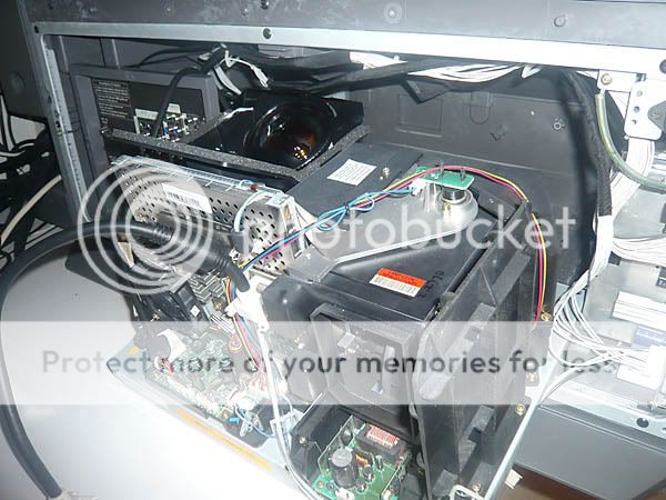
Pulling out the projector assembly and testing the fans, found them to be working perfectly.  So I started searching technical websites and disassembling the unit further. Many users seem to have experienced problems with loud buzzing and distorted colors, and most stemmed from a broken color wheel.  The color wheel is not visible in this image, but can be found to the right of the projector lens, underneath the black plastic cover with the square white sticker.


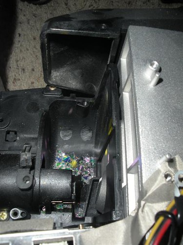
Getting down to the color wheel I find that it is clearly broken.  There are glass shards in the bottom of the housing and the wheel itself is broken (see below).


This is what the broken color wheel assembly looked like.  The edges should be uniform circular, and the wedge missing should be there as well.  It appears that the wedge came as it was spinning and then crashed into the wheel, shattering itself and damaging additional panels. Now unbalanced, the timing of the color system is shot and the picture appears as a black and white image with random colors applied.
Broken BP96-00674A Color Wheel

When ordering a new color wheel, take note of your model number carefully.  My unit is a model HLR5067WX (note the X on the end) and has an L3 chassis, which requires a model BP96-00674A Color Wheel (~$125 on Amazon).  The model HLR5067W has an L6 chassis, and uses a model BP96-01103A color wheel (~@88 on Amazon). Both model chassis' and color wheels look nearly identical, with the only apparent difference being a only a few millimeters difference in the mounting rails.  But they are NOT interchangeable.


Saturday, June 18, 2011

Samsung DLP TV repair - Part 1


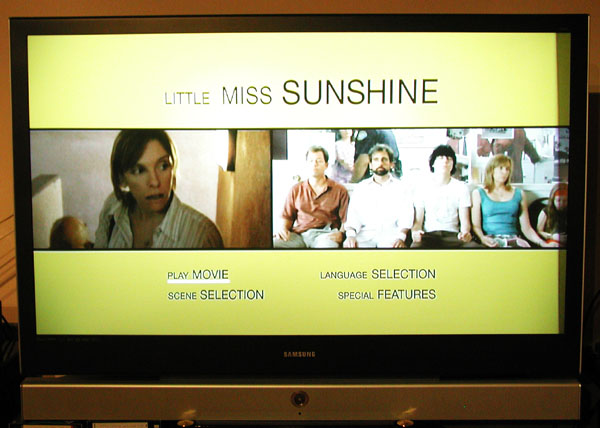
SamSung HLR5067WX 50" DLP TV
I recently got a free SamSung HLR5067WX 50" DLP TV from a relative. It was working and started making a loud buzzing noise and the picture went crazy. I figured that the fan had failed and a chip had overheated, so I brought it home to see if I could repair it.  With any luck the chip isn't cooked, and a new fan will bring her back to life.


Tuesday, May 10, 2011

Has Coleman betrayed it's heritage?

I was unsuccessfully searching for a replacement grease pan (p/n 9990-4651) for my Coleman 5300 grill, when I ran across this blog entry.
No Spare Parts; No More Coleman Grills: " I’ve purchased my last Coleman grill. The grease pan—a 19”x32” pan (p/n 9990-4651)that catches all the stuff that doesn’t stick to the other parts—is not usable and can’t be replaced. There is no replacement item. ..."
Oddly, they warrant the burners for life ($50/set) and the electronics for 7 years ($34/set), but a $10 tin pan that you can't live without is "Temporarily Unavailable".  That is, unless you call in which case you find that "temporary" actually means "permanent" Like the previous author, I too am unlikely to purchase another Coleman grill. Why pay premium for products with replaceable parts if the parts aren't in fact replaceable?

Anyway, I think that Coleman has lost it's way.  And I find that a bit sad given that my father and I have been depending on (and enjoying) Coleman products for well over over half a decade. 

Tuesday, August 10, 2010

SuperSprint Repair - Pt 9 - Repair complete!


I played my game last night for the first time in 10 years. I am VERY grateful to all who helped me on this project.

Monday, August 09, 2010

SuperSprint Repair - Pt 8 - Drawing a blank, or not!

Victory! Well, actually just progress. I replaced Q201 & Q202 in the blanking circuit. That gave me a picture (FINALLY!), but it was still heavily blue biased (see pic 1). For good measure, I also replaced Q205 & Q208 in the main board blue drive circuits. For a few glorious minutes, I had correct color. Then it returned to blue biased again???


Next, I swapped the Red and Blue neck board transistors (Q401, Q403) with no change. After that, I pulled all the pins from the RGB feed to the neckboard (except T) and began playing mix-n-match with jumpers. No matter what happened, sending a signal to the blue input resulted in a blue that was too strong. Diagnosis; Problem is not in the mainboard.


To diagnose the problem further, I lifted the final current limiting resistors (3) feeding the RGB pins on the tube. No picture (black) as expected. But to my surprise when I cranked up the screen control near max, the image began appearing faintly on screen. (cross talk?). Anyway, I jumpered from the each drive circuit to KR, KG, KB. Consistently, whenever any signal was applied to KR or KG, it looked normal (pic 2). But when that same signal was applied to KB, I got an overly bright blue screen (pic 3). Diagnosis; Problem is not in the neckboard.


At this point, I believe there is a problem with the blue gun. But, testing it against H, and every other pin on the neck I get no short and >1Mohm resistance. And the blue ends at the well defined edge of the raster. However, if I turn up the screen, I get raster lines that are blue, and a blue "background" where there should be white raster.

By playing with the drive pots and the screen control, I manage to get a proper picture (pic 4), but the blue pot is all the way down and the other pots are all the way up. Also, the screen seems set a little high at about 11o'clock. At 9 o'clock there is practically no image at all. It's usable, but I wonder about running these pots hard at one end or the other.


Conclusion: It's playable but I'm still not certain where the blue problem lies. I had speculated that the problem was a "hot" blue gun and a weak red and green because of how I set the pots. However, with a good picture on screen, final K voltages are R-87.2, G-88.7, B-101.0 vs 88.3VDC spec for all. What confuses me is that *dropping* the blue gun to 88.3 dramatically increases blue bias and creates raster lines on screen. Perhaps's an inverse coupling of K voltage and screen brightness is normal and I just don't understanding completely how the CRT works.

SuperSprint Repair - Pt 7 - Feeling Blue

A fellow collector suggested it may be the tube and reminded me that it is possible that the blue gun is shorted and staying on when the heater has power, creating the blue screen. I'm not sure about that as I thought losing blue when I left the blue gun out of circuit would contraindicate a gun failure?  Also, I was under the impression that a shorted gun wouldn't leave a clean black border between the image and the tube edge. Hmmm.... To be sure I tested H-KG, H-KB, H-KR and found no shorts between the heater and any of the colors.

Next, I unseated two of the resistors before the neck socket, removing input to those guns. With only green remaining, I got the image above, only in green. When I jumpered in Red off the green drive next circuit (pre-resistor), same image in yellow (red+green=yellow). When I jumpered in blue, I got a light cyan. From this, it appears that all my tube colors are functioning properly as yellow and cyan are the secondary colors of the respective pairs.

Not knowing where to turn, I tested all the resistors on the neck board (in spec), checked the pots against one another (same), swapped Q401 (green) and Q403 (blue), and re-flowed ALL of the neckboard (400 series) connections. When tested, I get the same image pictured above, only in white (YEA!!). Not there yet, but it appears I may have solved the dominant color issue.

Before calling it quits, I pulled and tested Q201, Q202 in the blanking circuit. I don't have a control to compare them to, but they tested similar to one another with ~0.694 across one junction and open across all others. I think I will replace these for good measure.

SuperSprint Repair - Pt 6 - New Voltage Regulator

Replacing the VR & HOT brought my B+ back up to 122.5V got me raster. Not white raster, but bright blue. Still not out of the woods yet, as all I can get is a blue screen with regularly spaced horizontal and diagonal lines (see green pic earlier in this, substitute blue for green). Lines are present in the screen shown, but not visible in the photograph.

I removed the Q403 (blue drive - neckboard) and the main body of the screen is light blue with bright blue diagonal lines. Top and bottom edges are well defined with a black border. L&R are scalloped in, forming a sort of letter "I" shape. Removing the RBG connection between the main board and the neck board cleaned up the edges nice and straight once, but that may be a fluke as I haven't been able to reproduce it again.


So far;

- Removed game PCB feed, no change.
- Removed RGB feed from chassis to neckboard, no change.
- Removed Q403 (blue drive transistor), colors lightened, images remained the same.
- Lifted R415 where it meets the neckboard. Color changed to yellow, but the image is the same.

I'm stumped. Fromm diagram suggests Q201, Q202, but with the neck feed disconnected, they are out of circuit. Am I seeing a failure in the oscillator and hence no change when it's disconnected from the neckboard?

Monday, July 19, 2010

SuperSprint Repair - Pt 5 - Flyback replacement

Yea!! The replacement flyback for my K4900 monitor arrived from ArcadeCup today, and tonight I may get to see my SuperSprint's face for the first time in almost 10 years! First, I begin by getting all my tools and parts together.

Fig 1 - Chassis and new flyback.


Desoldering the old flyback is a tedious process involving lots of time, patience, and soldering wick. The posts are fairly large solder joints, so braid was a little slow. Here is where I really wish I had a solder sucker.

Fig 2 & 3 - Old flyback removed from chassis.


Taking the old flyback out took forever, but installing the new one took just a few minutes. The trickiest part is holding it still until you can get a few colder connections in place. To simplify that, I press the flyback into position and use a pair of hemostats to grip the legs and hold it tight to the circuit board. One connect on each side, and you can remove the hemostats. Since the legs are all in a circle, and the flyback is large, the next 8 connections are quick and easy.

Fig 4 - Brand new flyback in place


With everything in place, it's time to give her a test run. At first, she displays a very nice playfield, a little out of focus, small, and washed out but otherwise colored correctly. A few degrees on the focus pot, and she looks better. Suddenly, the screen goes pure bright green with horizontal lines every 1" or so. I shut her down and check all connections but find nothing amiss.

Second try is a repeat of the first. Starts out normal, goes green, and then after awhile, the screen goes dark for about 60 seconds and comes back with a definite blue tint.

Fig 5 & 6 - Blue shrunken screen
Note: Circular "waves" are a camera artifact.


Checking B+ at TP91 reveals it's only 100VDC and Fromm's points to the voltage regulator. This is a new regulator, but it's a slightly different part number (STR381 vs STR380). Not having another STR380, I decide to try the original. Bad move. She blew the main fuse immediately on power up. After replacing the main fuse and STR381, she no longer has a picture or heater glow. To make matters worse, while testing various voltages I see a ribbon of smoke and smell R503 overheating. I shut her down, and find the HOT is shorted. Man I hope it's just the HOT and VR IC.

Tomorrow I'll call Zannen again and order another VR and HOT...